耐候性試驗
Weathering Testing
咨詢熱線
18566398802
SAE J1401-2003
SAE J1401-2003標準介紹
SAE J1401標準簡介
SAE J1401是關于用于道路汽車液壓系統的液壓制動軟管的測試標準,SAE J1401同時也指出了區分各大生產廠商的標準方法。本版本標準為J1401-2003,后續數字指定的是最近標準修改被采用的年份。以下為部分英文標準原文,出于版權保護,如需SAE SAE J1401標準全文或SAE SAE J1401中文版本標準,請垂詢客服人員。
1. Scope
This SAE Standard specifies the performance tests and requirements for hydraulic brake hose assemblies used in the hydraulic braking system of a road vehicle. It also specifies the methods used for identification of the hose manufacturer.
This document applies to brake hose assemblies made of a hose fabricated from yarn and natural or synthetic elastomers and assembled with metal end fittings for use with nonpetroleum-base brake fluids as specified in SAE J1703 and SAE J1705.
The nominal internal diameter of the brake hose shall fall within one of the following values:
a. 3.5 mm or less (1/8 in or less)
b. 4 to 5 mm (3/16 in)
2. References
2.1 Applicable Publications—The following publications form a part of this specification to the extent specified herein. Unless otherwise indicated, the latest issue of SAE publications shall apply.
2.1.1 SAE PUBLICATIONS—Available from SAE, 400 Commonwealth Drive, Warrendale, PA 15096-0001.
SAE J1703—Motor Vehicle Brake Fluid
SAE J1705—Low Water Tolerant Brake Fluids
2.1.2 ASTM PUBLICATION—Available from ASTM, 100 Barr Harbor Drive, West Conshohocken, PA 19428-2959.
ASTM B 117—Method of Salt Spray (Fog) Testing
2.1.3 ISO PUBLICATION—Available from ANSI, 11 West 42nd Street, New York, NY 10036-8002.
ISO R147—Load calibration of testing machines for tensile testing of steel
2.2 Related Publications—The following publications are provided for information purposes only and are not a required part of this document.
2.2.1 SAE PUBLICATIONS—Available from SAE, 400 Commonwealth Drive, Warrendale, PA 15096-0001.
SAE J1288—Packaging, Storage, and Shelf Life of Hydraulic Brake Hose Assemblies
SAE J1406—Application of Hydraulic Brake Hose to Motor Vehicles
2.2.2 ISO PUBLICATION—Available from ANSI, 11 West 42nd Street, New York, NY 10036-8002.
ISO 3996—Hydraulic brake hose assemblies—Non-Petroleum hose hydraulic fluid standard
3. Definitions
3.1 Brake Hose Assembly—A brake hose equipped with end fittings for use in a brake system.
3.2 Brake Hose—A flexible conduit manufactured for use in a brake system to transmit and contain the fluid pressure medium used to apply force to the vehicle's brakes.
3.3 Brake Hose End Fitting—A coupling, other than a clamp, designed for attachment to the end of a brake hose.
3.4 Permanently Attached End Fitting—A coupling designed for permanent attachment to the ends of a brake hose by crimping or swaging.
3.5 Free Length—The linear measurement of brake hose exposed between the end fittings of a brake hose assembly while maintained in a straight position.
3.6 Leaks, Burst—The loss of test fluid from the brake hose assembly other than by the designed inlet(s) and outlet(s).
3.7 Cracking—The interruption of a surface due to environment and/or stress.
3.8 Hose Internal Diameter—A dimensional description of the nominal inside diameter that is printed on the hose cover. This dimension is to be used to calculate the gage size for the constriction test.
EXAMPLE—3 mm
4. Performance Tests
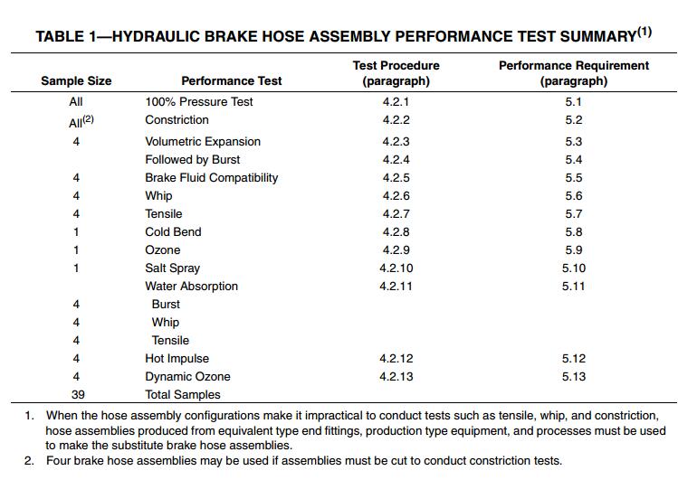
Performance tests for hydraulic brake hose assemblies include all of the tests listed in Table 1. These tests shall be conducted on each I.D. size and type1 from each hose manufacturer. A change in hose construction, that is, a change in material or a change in the manufacturing method, shall require a complete performance test. Accordingly, each coupler shall conduct the performance test on each coupling crimp design for each hose construction. A change of coupling crimp design shall require a complete performance test. Variations that do not influence the integrity of the hose coupling joint, such as variation in thread size, port dimensions, hex size, and the like, shall not be considered new design. The sample sizes listed in Table 1 represent minimums for validation of a production process. The manufacturer of the hydraulic brake hose assembly is responsible for conducting appropriate design verification exercises and for controlling the production processes such that any hose assembly provided for sale or use on a vehicle will be capable of meeting the performance requirements listed in Section 5 when subjected to the tests listed in Table 1, performed per the procedures and conditions described in 4.1 and 4.2.
4.1 Test Conditions
The assemblies for each performance test shall be new and unused and shall be at least 24 h old. The last 4 h prior to testing shall be at a temperature of 15 to 32 °C (60 to 90 °F). Prior to installation of the hose assembly on a whip or cold bend test, all external appendages such as mounting brackets, spring guards, and metal collars shall be removed or long tubes shortened, or both. The temperature of the testing room shall be between 15 and 32 °C (60 and 90 °F) for all tests except brake fluid compatibility, cold bend, hot impulse, ozone, dynamic ozone, salt spray, and water absorption. SAE Referee Brake Fluid, RM 66-05, should be used for all tests requiring brake fluid. Different test results may be obtained using different fluids.
4.2 Test Procedures
4.2.1 100% PRESSURE TEST—The hose assembly shall be subject to a pressure test, using inert gas, air, water, or brake fluid as a pressure medium. Brake fluid shall meet SAE J1703/J1705. The test pressure shall be 10.3 MPa (1500 psi) minimum, 14.5 MPa (2100 psi) maximum for inert gas and air and 20.7 MPa (3000 psi) minimum, 24.8 MPa (3600 psi) maximum for water and nonpetroleum-base hydraulic brake fluid. Special care should be taken when gas or air is used. Under the pressure specified, gas or air is explosive if a failure should occur in the hose or hose assembly. The pressure shall be held for not less than 10 nor more than 25 s.
4.2.2 CONSTRICTION TEST—For qualification and lab testing, the constriction of the hose assemblies shall be measured with a gage plug as shown in Figure 1. Hold the assembly vertically at the fitting and insert the “A” diameter portion of the constriction gage into the end of the fitting. Allow the gage to drop of its own weight for the full length of the probe. The time required for the gage to drop shall not exceed 5s. Repeat this step for the other end of the brake hose assembly。
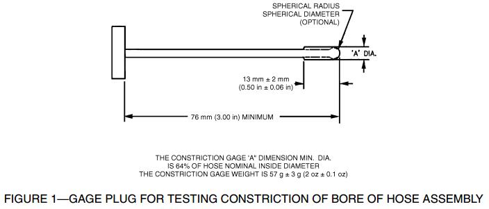
The design of some fittings makes it impossible to insert the gage plug externally. For these assemblies, insert a special elongated gage plug into the opposite fitting and pass the probe through the hose, into and through the crimped area of the fitting being tested. If the gage plug becomes misaligned at the entrance to the second fitting, it may be necessary to align the hose to allow the plug gage to pass through. The special gage plug shall meet all the requirements of Figure 1, with the exception of the 76 mm (3 in) length, which must be increased appropriately so that its tip will extend past the hose opening. Some brake hose assemblies have fittings on both ends, brackets, and/or center fittings that cannot be entered with a gage plug. Cut these assemblies 50 mm ± 3 mm (2 in ± 0.1 in) from the end of the fitting and then test with the plug gage. (Reference Table 1, footnote 2).
4.2.3 VOLUMETRIC EXPANSION TEST—The expansion test is designed to measure, by fluid displacement, the volumetric expansion of the free length of assembled hydraulic brake hose when subjected to specified internal pressures. Water or SAE Referee Brake Fluid RM 66-05 should be used as a pressure medium.
4.2.3.1 If the specimen used in this test has been subjected to a pressure above 20 MPa (2900 psi) using any medium prior to this test, allow it to recover for 15 min.
4.2.3.2 Carefully thread the hose assembly into the adapters designed to seal in the same manner as in actual use. Do not twist. Maintain the hose in a vertical, straight position, without tension, while under pressure.
4.2.3.3 Bleed all the air from the system by allowing approximately 0.25 L (0.5 pt) of brake fluid or water to flow through the hose assembly and into the buret. Removal of air bubbles may be facilitated by moving the hose back and forth. Close the valve to the buret and apply 20.0 MPa +0, ?0.14 MPa (2900 psi +0, ?20 psi) to the hose assembly. Within 10 s, inspect the hose assembly for leaks at the connections and then release the pressure completely in the hose. Adjust the brake fluid or water level in the buret to zero. With the valve to the buret closed, apply 6.9 MPa +0, ?0.14 MPa (1000 psi +0, ?20 psi) to hose assembly and seal this pressure in the hose within 5 s ± 3 s. Within 3 s, open the valve to the buret for 10 s +3, ?0 s and allow the brake fluid or water level in the expanded hose to rise in the buret. The brake fluid or water level in the buret should be constant within that time period.
4.2.3.4 Repeat the preceding step two times, so the amount of brake fluid or water in the buret will be the total of the three expansions. Measure this buret reading to the nearest 0.05 cm3.
4.2.3.5 The volumetric expansion is calculated by dividing the buret reading by three and subtracting the calibration factor. This figure divided by the free length in meters (feet) will give the volumetric expansion per meter (feet) of hose.
4.2.3.6 Readjust the brake fluid or water level in the buret to zero as previously stated and repeat the procedure to obtain the expansion at pressures of 10.3 MPa +0, ?0.14 MPa (1500 psi +0, ?20 psi) and 20 MPa +0, –0.14 MPa (2900 psi +0, –20 psi.) If the pressure in the hose should inadvertently be raised to a value above that specified, but not above 24 MPa (3500 psi), completely release the pressure and allow the hose to recover for at least 15 min and then repeat the test. If the hose was subjected to a pressure above 24 MPa (3500 psi), repeat the test using a new brake hose. If at any time during the test an air bubble flows out of the hose, repeat the test after allowing at least 3 min for the hose to recover.
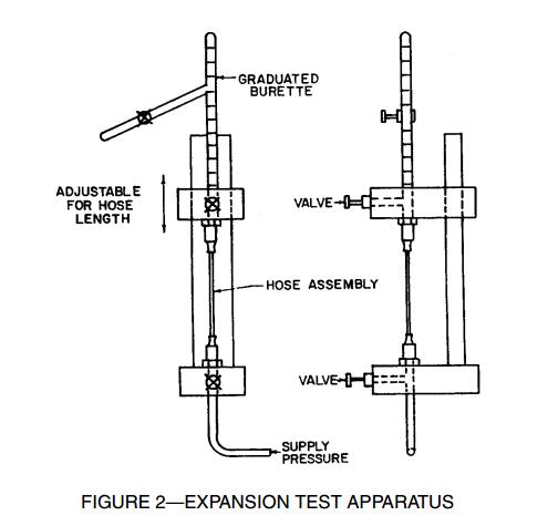
4.2.3.7 Test Apparatus—Test apparatus shall consist essentially of the following:
a. A source for required fluid pressures, test fluid consisting of brake fluid or water without any additives and free of air or gas bubbles.
b. A reservoir for pressure gages, fittings where the hose assembly may be mounted vertically for application of pressure under controlled conditions.
c. A graduated buret with 0.05 cm3 increments for measuring the volume of liquid corresponding to the expansion of the hose under pressure.
d. Plumbing hardware as required.
All piping and connections shall be smooth bore without recesses or offsets so all air may be freely removed from the system before running each test. Valves shall be capable of withstanding pressures involved without leakage. See Figure 2.
4.2.3.8 Calibration of Apparatus—The apparatus shall be tested prior to use to determine its calibration correction factors. These correction factors should be established at pressures of 6.9, 10.3, and 20 MPa (1000, 1500, and 2900 psi) using an assembly, which shall consist, for example, of 1.52 mm (0.060 in) minimum wall, hydraulic steel tubing with a free length of 305 mm ± 6 mm (12 in ± 0.2 in), and 6.3 mm (0.25 in) outside diameter. All fittings and adapters used in testing of the assembly shall be in this system. This may require the attachment of the tubing to the brake hose fittings in the case of special end configurations. The calibration correction factors shall be subtracted from the expansion readings obtained on the test specimens. The maximum permissible calibration correction factor shall be 0.08 cm3 at 10.3 MPa (1500 psi).
4.2.4 BURST STRENGTH TEST—Connect the specimen to the pressure system and fill completely with water or SAE Referee Brake Fluid RM 66-05, allowing all air to escape. Removal of air bubbles may be facilitated by moving the hose back and forth. Apply 27.6 MPa +0, ?1.4 MPa (4000 psi +0, ?200 psi) pressure at the rate specified in 4.2.4.1 and hold for 2 min +0, ?10 s. At the expiration of this hold period, increase the pressure at 172.5 MPa/min ± 69 MPa/min (25 000 psi/min ± 10 000 psi/min) until the hose bursts. Read the maximum pressure obtained on the calibrated gage to the nearest 1 MPa (100 psi) and record as the bursting strength of the hose assembly.
4.2.4.1 Test Apparatus—The apparatus shall consist of a suitable pressure system where hose is connected so that controlled and measured fluid pressure may be applied internally. The pressure shall be obtained by means of a hand- or power-driven pump or an accumulator system and it shall be measured with a calibrated gage. Provision shall be made for filling the hose with water or brake fluid and allowing all air to escape through a relief valve prior to application of pressure. This is important as a safety measure. The hold and burst pressures shall be applied at a rate increase of 172.5 MPa/min ± 69 MPa/min (25 000 psi/min ± 10 000 psi/min). Since this type of hose withstands a minimum bursting pressure of 49 MPa (7000 psi) for 3.2 mm (1/8 in) and 34.5 MPa (5000 psi) for 4.8 mm (3/16 in), care must be taken that all piping, valves, and fittings are sufficiently rugged and adapted to high-pressure work. The apparatus described for the expansion test may be used when it conforms to these requirements.
4.2.5 BRAKE FLUID COMPATIBILITY, CONSTRICTION, AND BURST STRENGTH TEST
4.2.5.1 Attach a hose assembly or a manifold to which multiple hose assemblies may be attached, below a 0.5 L (1 pt) can reservoir filled with 100 mL of SAE Referee Brake Fluid, SAE RM 66-05 (see Figure 3)
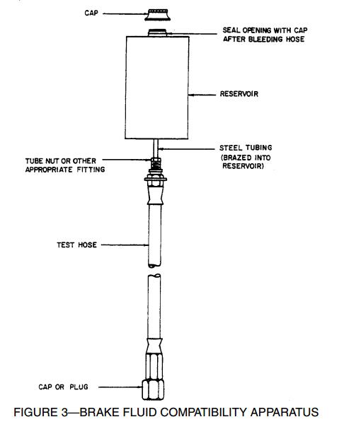
4.2.5.2 Fill the hose assembly with SAE Referee Brake Fluid RM 66-05, seal the lower end, and place the test assembly in a vertical position in an oven.
4.2.5.3 Condition the hose assembly at 120 °C +5, ?0 °C (248 °F +9, ?0 °F) for 70 to 72 h.
4.2.5.4 After completion of the heat aging period, remove the hose assembly and cool at room temperature for 30 min ± 5 min.
4.2.5.5 Drain the brake hose assembly, and within 10 min, determine, per 4.2.2, that every applicable diameter of the hose assembly is not less than shown in Figure 1.
4.2.5.6 The brake hose assembly shall be burst within 3 h using the test specified in 4.2.4.
篇幅所限未能詳盡,如需SAE SAE J1401標準全文或SAE SAE J1401中文版本標準,請垂詢客服人員。
溫馨提醒:本SAE J1401-2003可能存在更新的版本,建議尋找SAE J1401-2003的發行商確認。
 耐臭氧老化試驗機
 粵公網安備 44060402000067號